How do I build an electroplating cell for depositing metals?
An electroplating cell for depositing metals, also known as an electrolytic cell or electroplating cell, is a device used to deposit a layer of metal on another metal through an electrochemical process. Here is a step-by-step guide to building such a cell:
Materials:
- Current source: A controllable DC voltage source.
- Anode: For example, a copper anode if copper is to be deposited, for some solutions a different anode must also be used - follow the instructions for the electrolyte.
- Cathode (workpiece): The piece of metal on which the other metal is to be deposited (e.g. a piece of jewellery).
- Plating solution: A solution containing metal ions of the metal to be deposited (e.g. copper plating solution for copper deposition).
- Tank: To hold the plating solution.
- Lead wires and crocodile clips: To connect the electrodes to the power source.
Set-up:
-
Preparation of the electrolyte solution:
- Fill the container with the electrolyte solution. For the deposition of copper, for example, you can use a copper plating solution.
- Fill the container with the electrolyte solution. For the deposition of copper, for example, you can use a copper plating solution.
-
Inserting the electrodes:
-
-
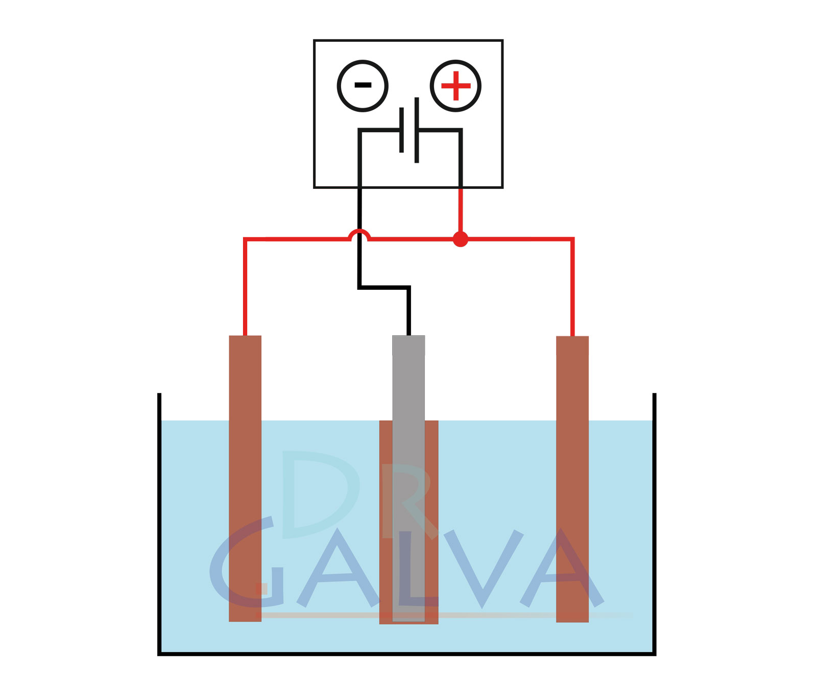
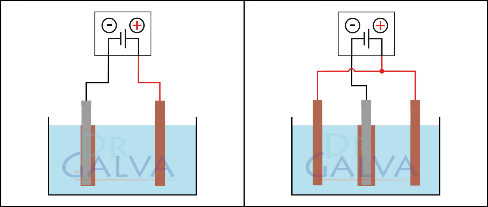
Anode: Insert the anodes (e.g. the copper plate) into the solution. These electrodes will provide the metal to be deposited. Two opposite anodes should be used in order to achieve a more even deposition. Refer to the diagrams. (If it is not possible to achieve such an anode arrangement, an even coating of the workpiece can be achieved by continuous rotation).
Please also refer to the section "Scattering in the galvanising process"
-
Cathode: Place the cathode (e.g. the piece of jewellery) in the solution as well. This is the workpiece on which the metal is deposited.
-
Anode: Insert the anodes (e.g. the copper plate) into the solution. These electrodes will provide the metal to be deposited. Two opposite anodes should be used in order to achieve a more even deposition. Refer to the diagrams. (If it is not possible to achieve such an anode arrangement, an even coating of the workpiece can be achieved by continuous rotation).
-
Connection to the power source:
- Connect the anode (copper plate) to the positive pole of the power source.
- Connect the cathode (workpiece) to the negative pole of the power source. This causes the cathode to become negatively charged, which leads to the metal being deposited on it.
-
Switch on the current flow:
- Switch on the current source. The metal ions in the solution (e.g. Cu²⁺ ions) are attracted to the cathode as it is negatively charged. The ions are reduced to neutral metal atoms and are deposited on the surface of the cathode.
How it works:
- Anode (copper plate): The anode partially dissolves due to the current flow, releasing copper ions (Cu²⁺) into the solution, thus the concentration of copper ions in the electrolyte solution remains constant:
Cu → Cu²⁺ + 2e⁻
- Cathode (workpiece): At the cathode, the copper ions (Cu²⁺) from the solution are reduced by the electrons and deposited on the workpiece as metallic copper:
Cu²⁺ + 2e⁻ → Cu
Important notes:
- Amperage and time: The amperage and the duration of the process determine the thickness of the deposited metal layer. Higher currents and longer times lead to thicker layers.
- Temperature: The temperature of the electrolyte solution can influence the deposition rate. Higher temperatures can accelerate the process, but also influence the quality of the layer.
- Purity of the electrolyte solution: Impurities in the solution can affect the quality of the deposited metal layer.
Result:
A uniform metal layer is deposited on the workpiece using this setup. This is the basic principle of electroplating, which is used in many industrial processes to coat metals and protect or refine surfaces.
General structure:

Comparison of the deposition:

| The anode and the workpiece are positioned opposite each other. More metal is deposited on the front side of the workpiece than on the rear side. The workpiece should be rotated at regular intervals. | Two anodes and the workpiece are located in the tank. It should be noted that both anodes should be connected to the same power supply unit. The workpiece is placed in the centre between the two anodes. This ensures a more even deposition. |


